We had the chance to listen to some phenomenal DIY planar hybrids at the 2016 Axpona show. After a few listening sessions with this design we knew a spotlight was in order. Below you can get some more info from the designer himself. Les….thank you for making the trip to Axpona and the Meniscus room to show off these DIY beauties. The pleasure was all ours!!
Designer: Leslie Heavner
The Parodies
The Parodies loudspeakers are three-way open baffle dynamic loudspeakers in a planar format, utilizing the miniDSP 4X10HD for active crossover and equalization duties. All drivers are homemade, aligned with no vertical offset, and offer rear output identical to front output both on and off-axis. The majority of the loudspeaker frame consists of mild steel plates and tubes welded together with a MIG welder, and most of the tubes are filled with sand to dampen any spurious ringing. The loudspeaker uses patented technology based on a very simple premise: when a current-carrying conductor is in close proximity to a single pole of a magnet, there will be a force exerted upon it.
Here are some additional specifications:
Drivers: Two 30″L x 5″W rectangular planar woofers; two 7.5”L x 2.5W” planar midranges, and a 2.5L” x 1W” planar tweeter in a horizontal M-T-M configuration, all in vertical alignment
Crossover: 300 Hz electrical 1st order Butterworth lowpass summed with electrical 3rd order Butterworth highpass
2.8 kHz electrical 4th order Linkwitz-Riley
Dimensions: 42″L x 15″W; stand footprint 24.25″L x 15.25″W
Weight: 55 lbs. each, including stand
Frequency Response: active equalization, so variable; currently -3 dB at 23 Hz
Suggested Ancillary Equipment: 6-channel solid state amplifier, 200 watts RMS minimum at 4 ohms with high damping factor
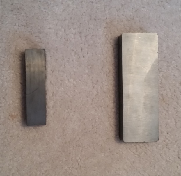
The dual side-by-side woofers are comprised of archival-grade e-flute cardboard with dual voice coils surrounding the columnar magnet structure between the diaphragms. The woofers measure 30″L x 5″ W; thus, they offer about 300 square inches of total surface area, roughly equivalent to about two 14″ circular woofers, if that size were available. I increased the depth of the ferrite (ceramic) magnets I purchased twofold, from 1″ deep in previous models to 2″ deep in this one, so this feature provides an extra long-stroke capability, theoretically allowing up to about a 1 7/8″ peak to peak displacement capability, assuming the suspension will allow for that type of excursion. The old versus new magnets are shown in the first photo.
Former 1″ Deep Magnets Versus Parodies’ 2″ Deep Magnets
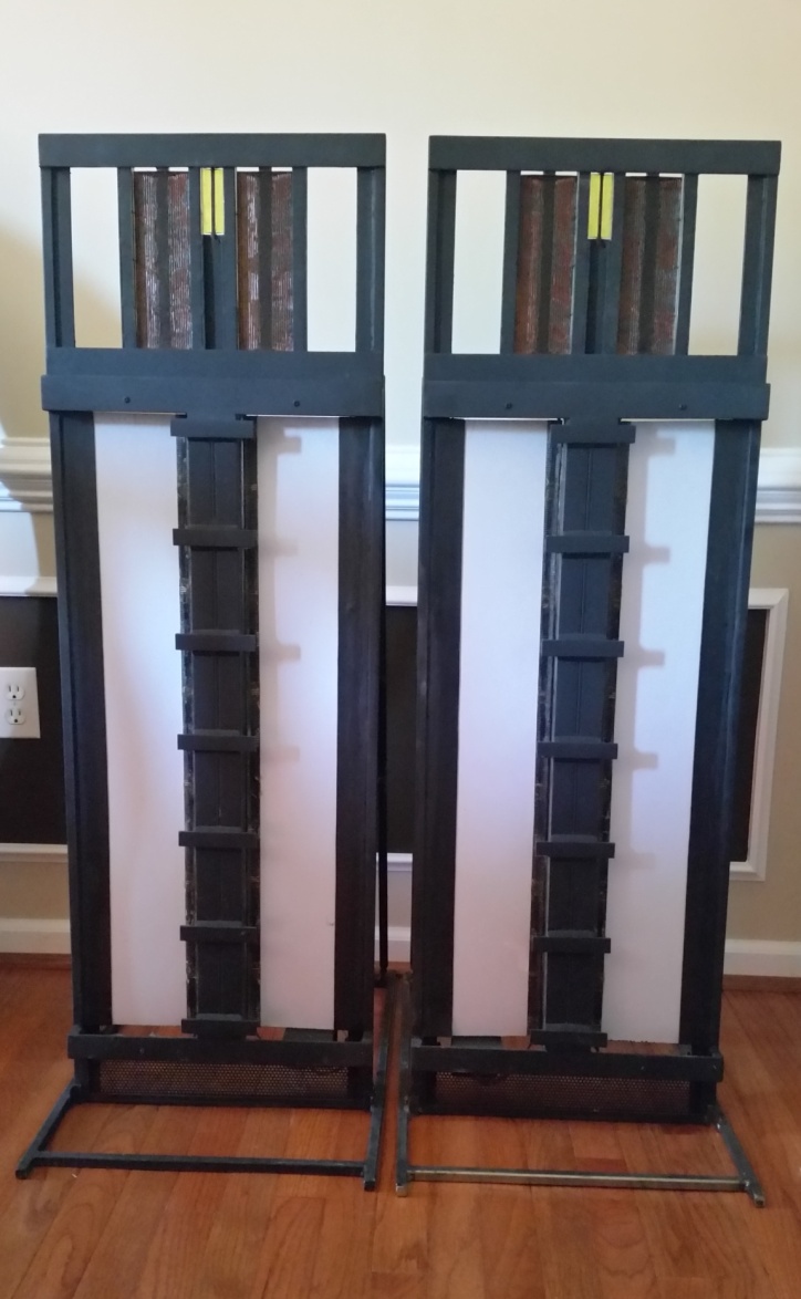
This photo is a side view of the loudspeaker with the new woofer magnets. The loudspeakers don’t look as sleek as my former loudspeakers with the thinner magnets, but the tradeoff is well worthwhile, in my opinion, due to the audible benefit.
Side View of Parodies Loudspeaker with 2″ Deep Woofer Magnets
In my previous model with the 1″ deep magnets, I would occasionally hear the woofers bottom out, particularly with certain action movie soundtracks or music with high-amplitude low bass content. A 45 Hz highpass filter helped only marginally, which made me decide to purchase the 2″ deep magnets I’m now using. I no longer experience this same issue, although there have been a couple of instances with movie soundtracks where I’ve seen the woofer diaphragms oscillate wildly for no apparent reason. This is presumably due to subsonic content that was inadvertently recorded on the soundtrack since there was no accompanying audible sound. In turn, this modulated the soundtrack contents, appearing to make it “skip,” much in the same manner a defective LP does. However, this is so infrequent I consider it not to be an important issue at all.
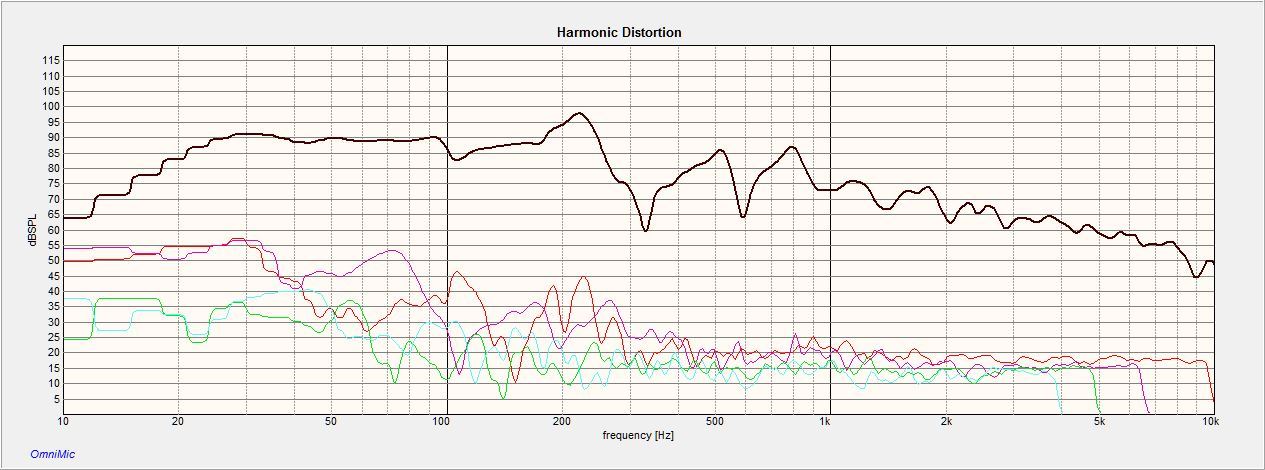
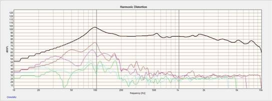
I generally use outdoor ground plane measurements for woofer frequency response measurements. The woofers are equalized to about -3 dB at 23 Hz with bandpass-type equalization instead of a shelving lowpass type. This allows for a more rapid falloff below 26 Hz, the diaphragm free-air resonance frequency, thus lessening cone excursion requirements. You will probably find you do not need a subwoofer, although these woofers do not pressurize a room or drone on like some subwoofers do. A few people who like this type of presentation may not find them suitable. The woofer harmonic distortion, 2nd through 5th, is shown below:
Woofer Harmonic Distortion, 2nd Through 5th
Here is a photo of the top rear of the woofers’ dual magnet columns, called stators, along with the voice coils, diaphragms, and a horizontal damper bar, one of many.
Woofer Stator, Top Rear View
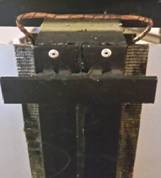
Notice the amber color of the insulated wire. This is 28 AWG copper wire with a 200 degree Centigrade insulation class, affixed to the diaphragm free edges on both magnet sides with fiberglass webbing and a high-temperature adhesive. This ensures that the voice coils will not be slung off during violent motion of the diaphragms, sure to be realized with a woofer. They are dual voice coils wired in parallel with a combined DC resistance of 3.8 ohms.
The ferrite magnets are encased in mild steel plates on all sides except the outer left and right sides in order to concentrate the magnetic flux where it’s most useful–toward the conductors–and to also eliminate some of the stray magnetic fields. The magnet columns have south poles facing outward, although both north poles facing outward would work equally well with a corresponding change of electrical polarity.
Since like-poles face outward, you guessed it–like poles also face inward–so their attraction to the steel plates must be sufficient to overcome the repulsive forces generated by the like-poles of the magnets in opposition. In other words, the steel should have a sufficiently high magnetic permeability. I found that a 3/16″ steel plate placed between the magnets’ like-poles, along with the front and rear plates, is sufficient to overcome this force. You may also use an adhesive as an additional aid, but I find this is unnecessary when dealing with the weaker ferrite magnets.
Also notice this is one place where I’ve used rivets instead of MIG welding the steel plates together–during final assembly after enclosing the magnets on all but the last remaining side. This is due to the fact that after the magnets have been positioned, high temperatures encountered while MIG welding the plates could demagnetize a portion of the adjacent magnets. This is due to the temperature exceeding their Curie point, the temperature at which a magnet becomes permanently demagnetized.
I have also forgone the usual arc-shaped voice coil at the top and bottom as you might normally see in a conventional planar magnetic loudspeaker. I previously used this configuration, but I found it was difficult to make minute adjustments to the voice coil to magnet gap when I used a piece of cardboard as a spacer. It would merely spring back to its former position when it was adjusted. Notice that the voice coil resembles the bottom part of an inverted right triangle. By pinching the ‘V’ part of the voice coil closed, it will facilitate placement of the diaphragm in tension against the pull of the rubber suspension located on the opposite “fixed” side of the same diaphragm, and also retain that spacing. Conversely, opening up the ‘V’ will create more of a gap, and it will also retain that gap setting.
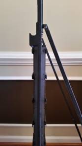
The horizontal damper bars are generally included on all my prototypes, as I have tried affixing various materials between the bars and diaphragms to aid in damping, and to more reliably recenter the diaphragm after each audio cycle has completed. Experiments have been mainly with butyl and neoprene rubber of different thicknesses, shapes, and hardness, all with mixed results. Here you can see a U-shaped damper affixed to the damper bar and diaphragm on an earlier prototype:
U-Shaped Damper Affixed to Damper Bar
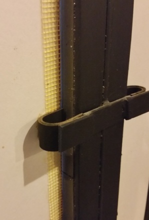
There are also dampers on the opposite side of the diaphragms in the same location. I tried S-shaped dampers for my newest extra long-throw woofers, but I removed them all, as they seem to compromise dynamics and maximum excursion capabilities while decreasing SPL . However, I will continue to experiment.
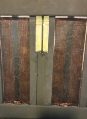
The upper part of the loudspeaker baffle houses dual planar midranges and a tweeter in a horizontal M-T-M configuration. A portion of the midranges’ magnets on either side of the tweeter are actually the opposite poles of the tweeter’s magnets, meaning they are shared–about as close an arrangement as possible for multiple horizontal acoustic sources. In addition, the tweeter is offset vertically from the midranges’ acoustic centers, further mitigating interference effects. The first photo shows the horizontal M-T-M layout, while the second photo highlights the shared midrange and tweeter magnets:
Horizontal M-T-M
View of Shared Midrange/Tweeter Magnets
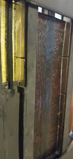
The midrange and tweeter diaphragms are made of 3 mil and 0.5 mil thick polyimide, respectively. Many of you know this material as Kapton, which is DuPont’s trademark name for their polyimide product. The magnets are N42 neodymium, each 2″ L x 1/2″ square, magnetized through their thickness.
The tweeter diaphragm is sandwiched between two 1/8″ square vertical steel bars located in the center of the diaphragm, which serve as the fulcrum point for the diaphragm movement. In other words, the diaphragm flaps like wings of a bird when an audio signal is applied. The same holds true for the midranges, but the center portion of the diaphragm is not sandwiched, but merely glued to a raised center bar. After comparing the front versus rear on and off-axis responses, I determined that it was unnecessary to add a similar bar on the front of the driver to obtain an identical response, front versus rear. I suppose this is due to the larger distance between the center fulcrum bar and outer magnets as opposed to the tweeter, along with the lower frequencies being dealt with.
So why don’t the woofers flap with this same bird-like motion, but instead flap like opposing pinball flippers? Why do they have their conductors affixed to the free inner edges of the diaphragms instead of the outer edges where the suspension is now located? This is due to the fact that if the magnets were located near the outside woofer diaphragms along with their conductors, and the fulcrum point with suspension was located between the two diaphragms, the upper and lower horizontal portion of the voice coils (currently the inverted right triangle portion) would be excessively wide. There would be no useful work performed by this part of the voice coils since there is no magnetic field there, and this current would be dissipated only as heat. Sensitivity would suffer greatly.
The like-poles of magnets face inwards toward the conductors for all individual drivers of the M-T-M arrangement, and polarity is established in the usual fashion, by connecting a cell, such as a 1.5 V cell, to observe the direction of diaphragm movement while noting cell connection polarity.
The midrange conductors are 30 AWG insulated copper wire, whereas the tweeter conductors are 35 AWG insulated aluminum wire. The midranges are wired in series, and the total combined DC resistance is about 3.5 ohms. The DC resistance of the tweeter is 2.5 ohms–which is a little low–but the amplifier doesn’t seem to mind. It’s actually not a bad load at all since it’s a tweeter, thus with a higher crossover point.
The exact method of affixing the wires to the diaphragm in that matter and ensuring they do not loosen with vibration, heat, and age shall remain a trade secret for now, although I’m sure many of you can figure this out with no problem, given a little thought.
So why have I opted to use wire conductors instead of foil as most manufacturers do nowadays? Well, I have tested foils extensively, but with mixed results. I’ve actually been very successful in etching plastic-backed foils by printing patterns directly on them with a laser printer, then etching the unprinted foil areas with an etchant solution consisting of ferric chloride, ferrous chloride, and hydrochloric acid. Here are some examples of my various experiments with tweeter diaphragms and materials, although I’ve experimented with midrange foils too. The foils are a little crinkled from being stuffed in a shoe box.
Tweeter Diaphragms and Materials
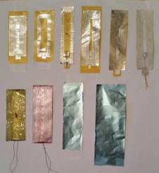
The first row are all etched polyimide foils of different sizes and shapes, with a few having different damping materials affixed. They are etched from a 1 mil polyimide film with a 0.3 mil aluminum foil bonded to both the front and rear. The manufacturer’s bonding process must be a trade secret since I can find no mention of it anywhere on their website. However, I assume the foils must be thermally bonded since they do not list an adhesive layer thickness in their specifications. The foil on both the front and rear allows for some flexibility in creating various tweeter diaphragms since you may have conductors on one side only, both sides, or one side with the foil left intact on the other. Notice the last tweeter diaphragm on the first row. It has leads soldered directly to the foil with damping material applied to the entire diaphragm on the soldered side. Yes, they make a solder with an aggressive flux that will bond wires to aluminum foil quite well, although it is easy to rip the wires off, as you can imagine. That’s why I always place any damping material, if used, on the soldered side. Notice the lead-in wires are soldered to the middle portion of the diaphragm, the part that always remains stationary.
The first diaphragm on the bottom row is the tweeter diaphragm used in the Parodies. The second diaphragm is one I used until just recently. It is also made from 0.5 mil thick polyimide just like the Parodies’ tweeter, but it also has a 0.1 mil sputtered aluminum layer, creating a mirror-like reflective surface on it. Although harmonic distortion levels were actually a little lower than the plain polyimide and wire tweeter I now use, I found it disconcerting to actually use it since the highly-reflective surface magnifies every little movement of the tweeter and draws your attention to it. I abandoned it for that reason, but if I ever use grille cloth, I may resume using it.
The last two examples on the bottom row are 0.5 mil thick polyester films with 0.3 mil thick foils bonded to them, the first foil products I used. These haven’t been etched yet. Most people know this film as Mylar, which is actually a DuPont trademark name for their polyester film product. Notice the light blue color it came in, which just happens to match my light blue/gray woofer diaphragm color quite well.
So why don’t I use foils since they at least look prettier doing the same job as wire does? It is due to this:
Polyimide With Foil Tweeter, Typical Harmonic Distortion, 2nd Through 5th
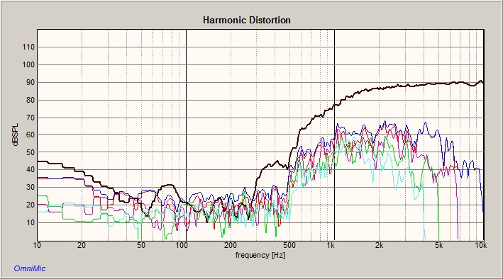
The 2nd through 5th levels of harmonic distortion are unacceptably high, although it really doesn’t seem to sound as bad as it measures.
In contrast, here is the harmonic distortion, 2nd through 5th, of the aluminum wire tweeters used in the Parodies:
Parodies Aluminum Wire Tweeter, Harmonic Distortion, 2nd Through 5th
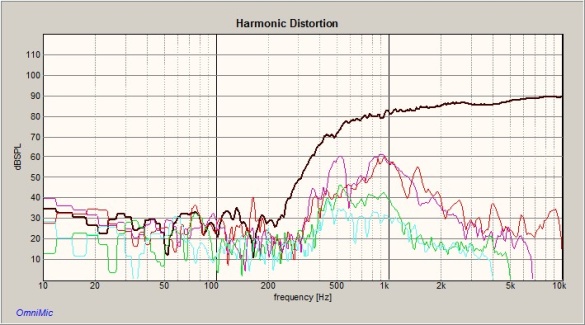
It can’t be crossed over super low either, but the distortion levels are much better than for any of the foils I have tested. I am actually at a loss to explain the difference in HD levels between the two since the main difference is that one uses a thermally-bonded foil for conductors, whereas the other uses 35 AWG aluminum wire, bonded with an adhesive. I’ve been testing the foils for years with different damping materials like felt, tissue paper, fiberglass webbing, spray-on adhesive, and so on, in order to duplicate the success I’ve had with aluminum wire. Although I’ve had some measure of success, I have yet to reach the same level attained with the aluminum wire tweeters.
Here is the harmonic distortion of a Parodies midrange driver, 2nd through 5th:
Parodies Midrange Harmonic Distortion, 2nd Through 5th
Although each driver is tested individually, I also test each completely fabricated loudspeaker, with all drivers in place and equalized with their crossover points set, one versus another for matching characteristics. I first measure one loudspeaker on axis at a specific location indoors, then mark that position with tape, and move the other loudspeaker to that position. Then, without moving the microphone, I measure the frequency response of that loudspeaker to ensure I’ve done a respectable job in fabricating the drivers. After all, they are homemade drivers. It’s not that accurate a process at lower frequencies indoors, but by using the exact same position each time with no other variables changed, it does tell me, regardless, if they are constructed similarly or not. Here is a comparative frequency response measurement of the Parodies taken at the same location indoors at one meter on the tweeter axis with 1/48th octave smoothing:
Parodies Left Versus Right Frequency Response
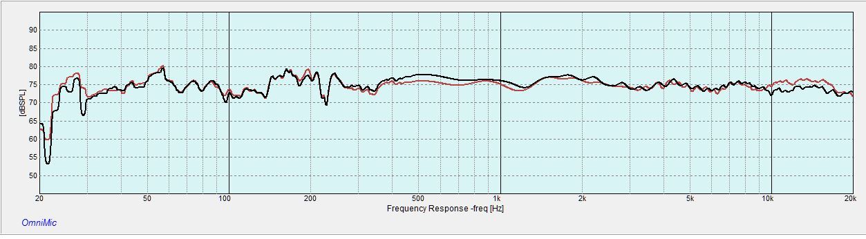
I think the driver matching is pretty good.
So how would I characterize the Parodies? Well, it would really mean nothing to you for me to wax poetic about their performance since I am their designer, and hence, considered to be biased. Let me simply put it this way: I am drawn to them so much, they are often a detriment to accomplishing any household tasks at all. They possess what I think is lacking in many of today’s loudspeakers: verve.
Leslie Heavner is the inventor/designer of the Parodies loudspeaker. He has been trying to perfect the loudspeaker since 2005 and was issued a patent in 2010 for the technology. For more information, please visit http://www.planarsonics.com.
Here’s a quicky gallery of the Parodies at Axpona 2015


