WinISD – a step by step tutorial for beginners!
by Johnny Richards
Note: this tutorial was written on a PC running Windows XP. The author has since upgraded to 64bit Windows 7, but has not verified compatibility of this version of WinISD in that environment.
Update: This version of WinISD runs fine on the authors 64bit Windows 7 machine. After install, navigate to the installation folder. On the authors machine, that is the following:
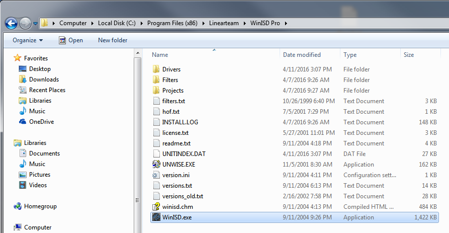
It might be different on your machine, so be sure to dig around. When you are in there, right click on the executable and select properties. Click on the “Compatibility” tab at the top, and make sure to select “Windows 98/Windows Me”.
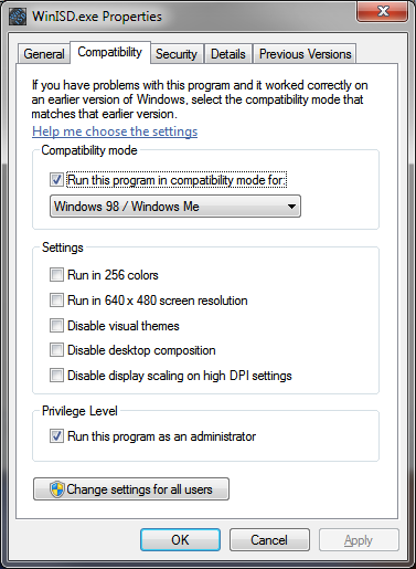
Some users have reported luck selecting one of the other modes, but the author had problems with all but 98/Me. Also select “Run this program as an administrator”, click “apply” and “ok” and start the software.
WinISD is a free, relatively full featured bass response modeling program. It is very popular due to price, flexibility and (after a short learning curve) ease of use. There are other tools out there, but they either require the end user to have an expensive software package installed (Microsoft Office), sport a high price (like Bassbox Pro) or are not as full featured and/or are optimized for more esoteric enclosure types (like HornResp).
There are three versions of WinISD available – a Beta version, an Alpha version, and a new version for Windows 7. There is some confusion here since there are actually two different pieces of software (Alpha and Win7 are very similar), and to my knowledge the driver databases are not interchangeable. The “beta” version could more properly be called “Lite” and the “alpha” version is called “Pro”. I don’t believe any development is currently in progress on either Beta or Alpha, however both versions are stable.
This tutorial will cover the usage of the “Pro” or Alpha version. To start, we will need to download the software package. Click here to download the executable to your computer. Run it and follow the directions on screen to install it to your computer.
When the install is done, fire up WinISD and you will get the following window:
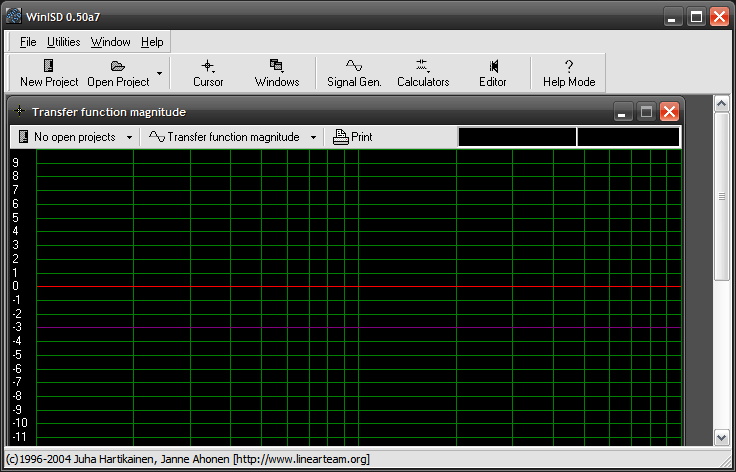
The program uses a standard Windows interface. Click on “file” on the top left and you will see some choices:
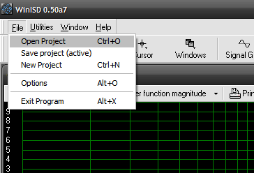
Choose “New Project” and the following dialogue box will show up:
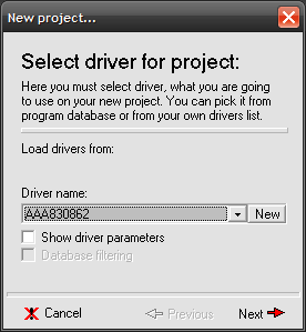
There are several options here. The pull down arrow will show your available choices from the included database of drivers. Just for learning the software, it is acceptable to choose one of the drivers in the database. However, they are often out of date – and nothing is worse than building your box before ordering the driver only to find out the manufacturer has changed the parameters!
We are going to assume you have a driver in hand with the full set of parameters. These parameters are known as Thiele-Small (T/S), and they are derived from and representative of, the driver’s electrical and mechanical properties. Describing and defining these parameters is beyond the scope of this article. An excellent source of driver parameters is the Parts Express forums (aptly named Tech Talk). The members are always willing to help out with modeling advice, and generously share measurements so you can assured of having reasonably up-to-date parameters. Parts Express also manages a broad product line called “Dayton Audio”, and they provide extensive and expansive documentation of those drivers.
In the “New Project” dialogue box the options are “Show driver parameters”, “New”, “Next” and “Cancel”. Clicking on “cancel” will close this dialogue and take you back to the opening screen. If you click in the check box next to “Show driver parameters” this will happen:
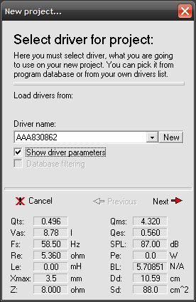
The dialogue box expanded and now shows the relevant T/S parameters. As you learn what these parameters mean and how they can be used to predict bass response, they will make a lot more sense.
For now, however, we will hide them by un-checking the box. Since we do not trust the database, we will enter our own driver. This process is very often the biggest stumbling block to new users of this software. The software does not tolerate “guessing” or “close enough” and so utilizes some pretty solid error checking when calculating unknown variables from input variables.
Without being familiar with the method of entering the data, it quickly becomes an exercise in frustration. There is no one in DIY speaker building who wish frustration on newcomers – especially when there is so much information available.
This is a good time to again mention the importance of accurate data when modeling anything to do with loudspeakers.
Although it is widely accepted that acceptable tolerances in driver parameters can be as high as 10%, this figure is misleading and rarely qualified. If, for example, it is assumed to be +/- 10%, that tolerance has the potential of stacking to 20% difference between two drivers. This deviation can actually create issues if two drivers share the same airspace, or are asked to reproduce the same audio pass band.
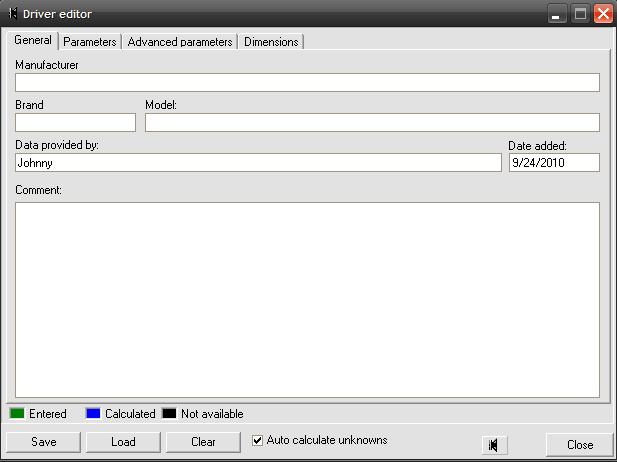
There is a lot going on here, but you are not required to actually enter anything on this screen (I believe the Windows 7 version will not let you skip this step). If you like, you can enter the pertinent information in the boxes. However, I have found the comments section to be very useful for documenting where I may have found the driver, who I purchased it from, what I paid, original plans for the driver, etc. It keeps all that information in one easily accessible place.
For this exercise, we assume we have a Dayton 8″ shielded DVC subwoofer that we are going to model. To get to the fun stuff we need to click on the “Parameters” tab at the top and this is where we enter our driver information.
We will need a source of data. Due to their well documented product line, we purchased our driver from Parts Express so obtaining the data is as easy as downloading the provided PDF file found here.
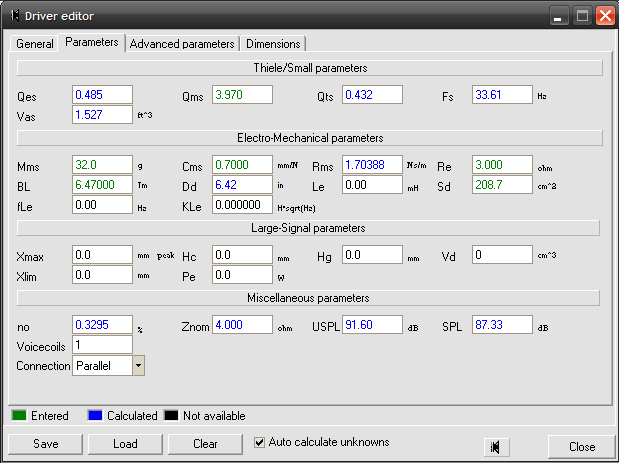
There is a lot of information contained in this spec sheet. Quite a few of them need to be copied into WinISD using the driver editor. So click on the “Parameters” tab and the view will switch to this:
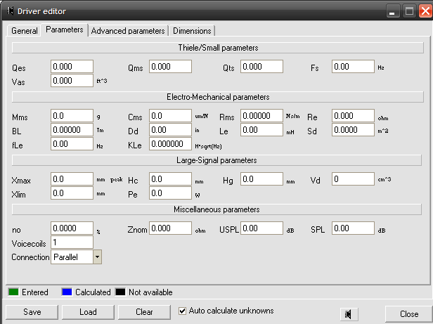
So there are a lot of empty spaces in this window, where to start? Well, the first thing I always do is ensure that the checkbox next to “Auto calculate unknowns” is checked. I then enter the parameters in the following order:
• I enter either diameter (Dd) or radiating area (Sd)
• I enter the drivers DC resistance (Re)
• I enter the drivers Qes
• I enter the drivers Qms
• I enter the drivers Vas
• I enter the drivers Fs
• I enter the drivers Xmax
If the driver cut-sheet you have chosen lacks the above basic data, it should be considered a red flag on quality. All reputable manufacturers will provide this data series, as it is the absolute minimum required for successful modeling. If it does not come with this data, you may have to invest in a measurement rig of some sort.
After entering the data, your Driver editor should contain numbers very similar to this:
Entering voice coil inductance (Le) is not advised due to WinISD making assumptions about top end extension based on Le that will result in inaccurate modeling. Voice coil inductance absolutely affects the top end on a driver, but it is never an inverse linear relationship like the modelers predict it to be.
You will notice there are some other parameters we can enter. These are related to thermal power handling (Pe), the mechanical limit of voice coil travel (Xlim), the length of the coil winding (Hc) and the height of the coil gap (Hg).
Some background on Xmax is warranted at this time, as it is not a parameter like Fs or Re. There are no rules governing Xmax declarations. Some manufacturers use the height of the gap divided by two minus the length of the coil – (Hg/2)-Hc. This is probably the method most commonly employed. The assumption is this number is the maximum distance of travel where 100% of the coil is still within the gap. It is theorized that when the voice coil leaves the gap, bad things start happening. There are others who measure Xmax by applying progressively larger amounts of power at a given frequency or frequencies and measuring distortion vs. excursion. When the THD (total harmonic distortion) reaches an arbitrary number they declare Xmax.
The problem with both methods is one of disinformation. The first method ignores distortion and tries to create an objective, mechanical parameter – however there are zero guarantees that audible distortion is not already rising before the calculated Xmax is reached. The second method holds more potential, but only if the manufacturer reveals the conditions resulting in the claim.
In the Dayton Audio spec sheet, you will see it simply calls out “Xmax – 6mm” Nowhere on this document does it state how this number was derived, so we have to take it on faith that the manufacturer is being honest with us and that we can expect reasonable performance within the claimed excursion limits.
I usually assume an honest manufacturer and use the claimed Xmax figure.
We are almost done with entering the driver data, and all that is left is to click the “Save” button. If you entered the data correctly, it will open the “File save” dialog box. If you made an error, it will pop up a message showing you exactly which data fields are incorrect.
WinISD has an annoying feature in that user generated driver files are stored in the same directory as the included files. What this means is that your painstaking work generating the above driver file will get buried below a bunch of drivers you will never use, or have likely never heard of! To compensate, this is how I would name the Dayton woofer we just created a file for:
AAA_Dayton_SD215-88_295-480
This will do a couple things for us. One, the AAA prefix will ensure all of our generated files are placed at the top of the drop down list. It also contains the manufacturer, manufacturer’s part number and the vendor part numbers.
Another alternative (on WinXP) is to navigate to C:\Program Files\Linearteam\WinISD Pro\Drivers and delete all of the files in that folder. These are the drivers included in the database that ships with WinISD Pro. I have not researched the new Windows 7 version for the procedure.
So we have now successfully completed one of the most frustrating parts of using WinISD to design our bass making machines – creating our own driver files. The fun stuff comes next!
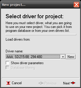
Now that we have reliable data to work with, we will click on “New Project” In the dialog box. The driver file we created in section one (if you followed the suggested naming protocol) should be the first in the drop down list in the New Project dialog box. The software automatically selects the first driver in the database.
If you read the instructions WinISD provides, it becomes apparent that the software truly is in early stage of development since there is a blank field which implies they intended to create two separate databases – one for the included drivers and one for our drivers. This feature has never been implemented, so the effect of that is the potential for our drivers to become buried with the stock drivers – hence the strongly recommended suggestions for naming convention, or the deletion of the database the software ships with.
Click on the “Next” button. Here we are presented with another dialog box which offers us several options – number of drivers, and normal or Isobaric loading:
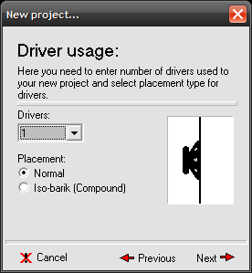
Since we are designing our first enclosure, we will keep it simple and choose a single driver with normal loading. As you progress and become more comfortable, it is fascinating to see what a hundred drivers would be capable of – or how small you can make an enclosure using Isobaric loading!
I have my doubts about the accuracy of multiple driver models in WinISD as I am not sure which assumptions they make with regards to serial or parallel connections. For the main purpose of the software (calculating the required volume for the driver), it is as accurate as any of the other modeling tools out there.
Click next to bring it to yet another dialog box with some more choices:
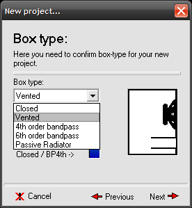
For now we will assume WinISD knows what it is doing by making the suggestion to go vented. Click next.
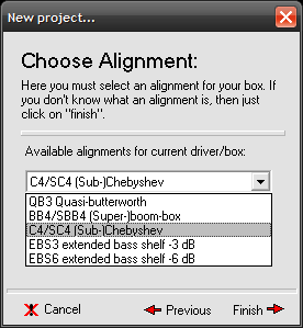
For this project, we will go with the WinISD suggested alignment – which is a vented, Chebyshev type.
The different types of alignments (Quasi-butterworth etc) are simply names given to specific behavior during the roll-off on the bottom end. They are rarely going to end up being implemented in a textbook manner so do not sweat it out over choosing one or the other.
This is a case of presenting too much information at one time, unfortunately. Information overload is a problem for most new people in any technical field – more so in as niche and randomly documented as is DIY audio!
Clicking on “Finish” will display the following window on your screen:
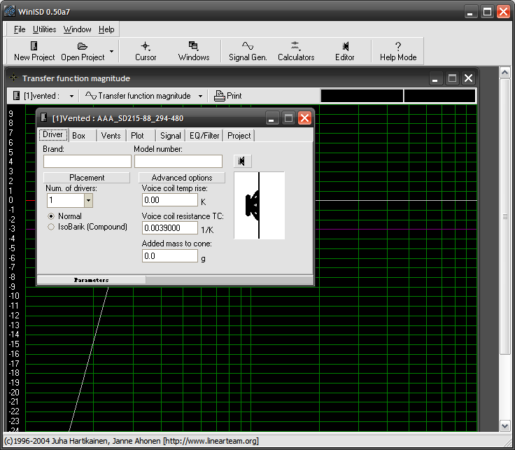
This is where I will maximize the WinISD main window, to allow myself more room to work. As you can see, the option window obstructs the chart be default. Maximizing the main window will not only present the chart contents fully, but will generate more real estate for multiple projects – when you get to that level.
WinISD calculated what it considered “optimum” based on the parameters provided. What they consider optimum is maximally flat predicted response. What a designer considered optimum will vary widely, of course. Again – as you progress you will realize that the program has to start somewhere, so a maximally flat alignment is as good as anything else.
Don’t get to taken in by the maximally flat way of looking at things, though. There is much more to learn and to understand before concentrating on the flat response aspect. I find understanding concepts and theory before considering a preference for certain results is a far better way to learn this stuff. So carry on with your experiments!
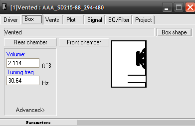
As you can see, WinISD determined that 2.114 cubic feet tuned to 30.64 Hz is the “ideal” enclosure volume and tuning for this driver.
Click on the “Vent” tab to see what the port needs to be:
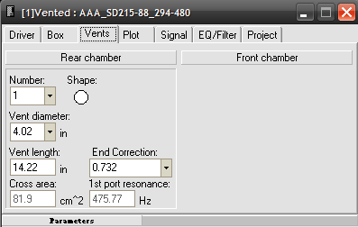
WinISD is calling for a 4.02″ port that is 14.22″ long. There is no such thing as a 4.02″ port so it is wise to click in the box, clear it and type in a simple “3”. There are rules of thumb about selecting the port diameter and WinISD chooses the 4.02” diameter by default. My personal rule of thumb is to use as large of a port diameter as possible. The length will change with changes in diameter – going larger results in longer ports. This is where designers must keep in mind their expected cabinet size and how to make sure the port diameter they chose will fit in that cabinet.
As a very general rule, I will use at least a 1.5” diameter with drivers up to 5”, a 2” with 5-7” drivers, a 3” with 8-10” drivers.
Going too small yields a greater chance of “chuffing” (noise from the port at higher volumes), while going too large results in ports that are simply too long to fit.
You can get a good visual of how port diameter affects port length in the next graphic. That is a considerable difference in length!
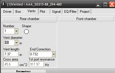
Now, we have a 3″ port that is 7.37 inches long. This is close enough to 7-3/8″ that we can feel safe calling it that. So now our enclosure is 2.114 cubic feet with a 3″ x 7-3/8″ port tuning it to 30.64 Hz.
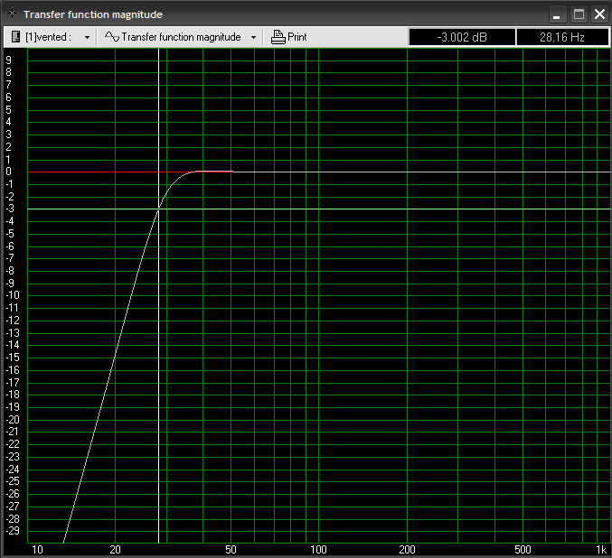
Looking now at our graph, we can now determine the actual frequency response of the driver in the enclosure. Left click on the graph and hold it down as you move your cursor around. You will see some numbers changing in the upper right hand of the screen. These are showing you what the amplitude in db of the frequency under the cursor is in relation to “0”. What we are looking for is the frequency at which the amplitude is -3db under the reference. In loudspeaker talk, this point is known as the “F3”. One of the most fundamental loudspeaker equations people learn is that doubling your power results in a 3db increase in output. The system F3 is an objective description of where the bass has rolled off enough to simulate power being halved. This is the most commonly accepted metric for expressing frequency response with regards to bass extension.
It is important to realize that this F3 is actually somewhat arbitrary based on the accepted assumption that we, as human beings, tend to struggle with perceiving differences less than 3db. So we use this metric (rather than F0 or F6 or F2.2) to convey that we start noticing a difference in output at this frequency. Most designers have internalized this metric and have no problems visualizing it – you will too.
In WinISD, you rarely get your mouse to where it says -3db exactly, but as you move your cursor around, you may notice the horizontal purple line below the red reference line. This symbolizes -3db from zero. Where your frequency response line (in this model it is silver) meets that purple line is your F3 point. When you click and drag the cursor to that point, WinISD will turn the purple line green when it is “close enough” to the -3db point.
As you can see in our chart, our predicted F3 is 28.16 Hz. This is a very low frequency, and this alignment will be able to cover the bass in the vast majority of music ever recorded as well as offering a reasonably good home theater experience – just watch out for those T-Rex foot stomps!
In all seriousness, however – this would make a very nice subwoofer for moderate listening levels, or tucked under a large desk.
WinISD has informed us that it would be “best” in an enclosure greater than 2 cubic feet. For some people, that is too much real estate to commit to a subwoofer – so we will talk a bit about altering enclosure size and the effect it has on bass response. For other people, the default alignment will not play deep enough so we will explore how to extend the response by tweaking cabinet size and tuning.
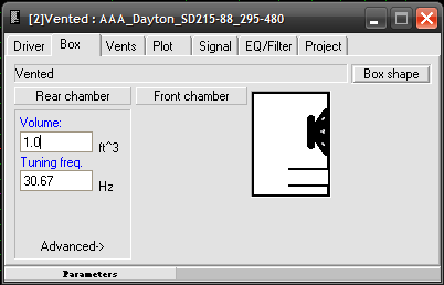
Our current WinISD approved alignment is 2.114 cubic feet with a 3″ x 7-3/8″ port. This is actually a fairly large enclosure for an 8″ driver, so let’s see what happens when we make it smaller. Click on the tab titled “Box”, and then click in the field titled “Volume”. If not already done, change the units to cubic feet. This is accomplished by clicking on the unit designation next to the volume field multiple times until “ft^3” is displayed. Change the 2.114 number to 1.0.
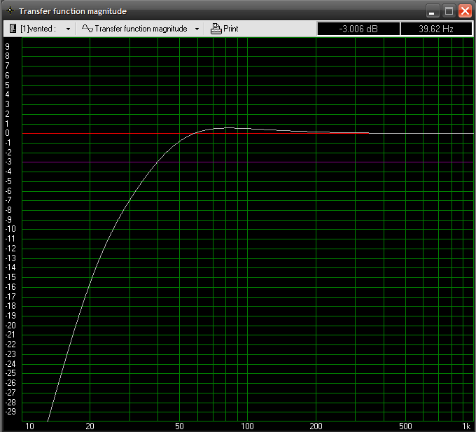
By making the enclosure approximately 1/2 the size of “optimum” and maintaining the same tuning frequency, we increased the system F3 to just under 40 Hz. This is not particularly low, but the enclosure is fairly small.
The smaller than optimal alignment has created a slight ripple centered at ~80 hz, but this is for all intents and purposes negligible as it is less than a db.
However, take a look at the “Vents” tab and see what happened to our 3″ diameter port:
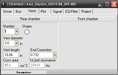
It is now calling for an 18″ long port! This is a length that is very difficult to fit into a 1 cubic foot enclosure!
You can build a one cubic foot enclosure in a shoebox shape and fit this port size, though. In fact, many commercial manufacturers and not a few DIYers do exactly that. Options, options always options!
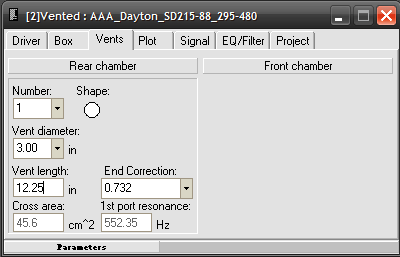
Now, let’s shorten that port to something that *will* fit into a cube shape of one cubic foot. This cube will be 14-1/2″ on each side. Rule of thumb is that the port terminus shall not be closer to any interior wall than the diameter of the port – so that leaves us with no less than 3″. This 3” is subtracted from the 14-1/2″ dimension on which we are mounting the port gives us 11-1/2″ to work with. We get some of that back because the port passes through the ¾” wall, so we can extend to 12-1/4” In the “Vents” tab, enter 12.25 into the box where it currently says “18.06” and then check out our response window:
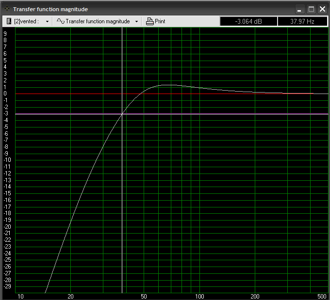
The F3 remains approximately the same, but there is now a 1.5db “ripple” centered at 65hz. In theory, this alignment is “wrong”, but in practice it will work very well for most types of music and the slight excess of energy in the 65hz region will lead to a perception of deeper bass than is actually being reproduced.
Targeting a lower F3 will require an EBS alignment. EBS is short for “extended bass shelf”, and can be used with drivers that are incapable of going low in traditional alignments.
First step is to click the “Box” tab again, and change the tuning frequency from 37.22hz to 25hz.
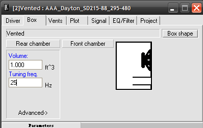
The next step is to increase the volume of the box to 3.0 cubic feet:
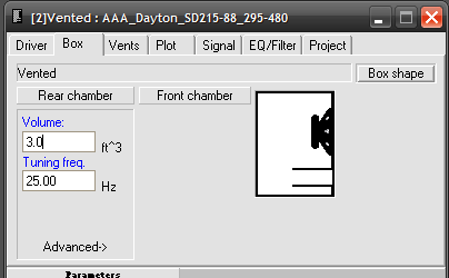
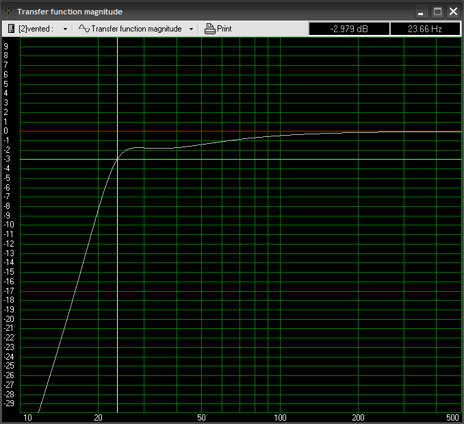
F3 is now at a very low 23.6Hz, at the expense of a very large cabinet. Notice the shape of the response, shelf-like isn’t it? This alignment could be very handy for home theater usage!
So we have now made the default box smaller and larger. Both examples are deliberately extreme, and meant to illustrate the effect on the response as we change the enclosure and/or tuning.
In my opinion, building somewhere between WinISD “optimal” and the extreme small example is probably the best use of this particular driver. Only experience will tell you if a certain alignment will work for a certain woofer – they are not all created equal on the bottom end regardless of how they model.
So now we move on to the filter side of things, because this really changes our alignment. Clicking the “add” button within the EQ/Filter tab, there are a number of different types of processing to apply to our alignment. Until now, we have been dealing with a theoretical amplifier source with a ruler flat response but in reality, most amps that will be used to power a subwoofer will employ a bandpass. This will filter frequencies above and below the pass band, which makes our modeling somewhat incorrect. As a rule of thumb, assume the subwoofer plate amp will use a 2nd order high pass filter and a 4th order low pass filter.
The high pass is generally fixed, and the low pass is usually adjustable across a limited range. However, some plate amps low pass may be defeated if they have an input labeled “LFE” and the high pass is sometimes user modifiable. Modifying the highpass will almost always require basic soldering skills to accomplish.
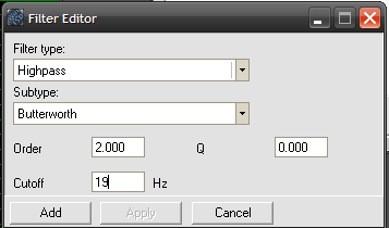
Stock plate amps that do not advertise any bass boost can be assumed to have a high pass centered at 18 or 19hz. So the first thing we will add to our model is the 2nd order high pass filter at 19hz. Click on “add”, and in the first field, expand your selection using the drop down menu button and select “Highpass”.
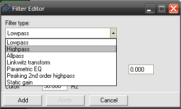
Leave the subtype set to “Butterworth”, the order set to “2”, and the Q set to “0”. Change the frequency from “20” to “19” and then click on “add”.
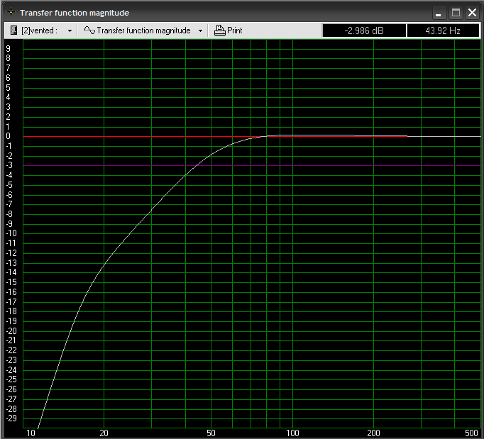
Notice the impact is fairly dramatic with our 3 cubic foot EBS alignment.
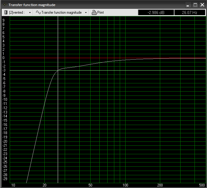
The modeled F3 is about 3Hz higher.
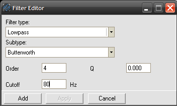
Restore the “ideal alignment” that WinISD suggested (2.113 cubic feet and 3” x 7-3/8” port), and we will now model the effect of a THX style low-pass crossover. Going back to the EQ/Filter tab, click on “add” and “low pass” is selected by default. Change the order to “4”, leave the “Q” at 0, and change the frequency to “80”.
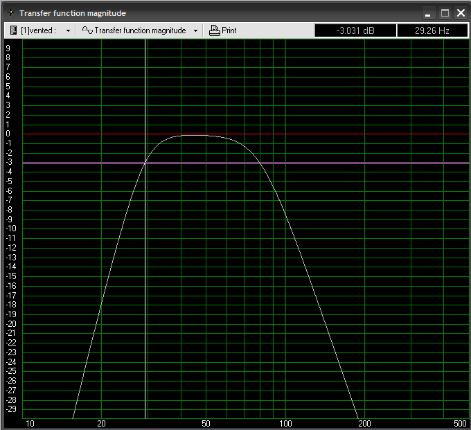
So there we have our first, basic ported model with two variations and the effects of the bandpass filter applied to the response.
Useful tips (in no particular order):
• When calculating diameter of the radiating surface of the driver, the prevailing rule of thumb is to measure from the midpoint on the surround – not the edge of the frame or where the cone meets the surround.
• If the Dd or Sd is not available and you do not have the driver physically in hand, the following suggestions based on advertised diameter should get you close enough
• For 4” drivers, 3.25”
• For 5” drivers, 3.875”
• For 5-1/4” drivers, 4.25”
• For 6.5-7” drivers, 5.125”
• For 8” drivers, 6.5”
• Note: some manufacturers inflate the driver size.
• On the “box” tab, click and hold your cursor on this icon:  . Now, move your cursor around as you hold your left click down. Cool, huh?
• Under the “signal” tab, change the entry in the “series resistance” field to 1.0 and notice the change in system response. Inductors have series resistance, and an expected resistance should be entered if the intent is to use passive crossovers.
• Enter your amplifier power into the “system input power” field. On the top of the chart window where it says “Transfer function magnitude” there is a drop down menu. Check out the “amplifier apparent load power (VA)” view, and compare it to the number you input. While you are in there, check out the cone excursion, SPL and Rear port velocity charts.
• Under the “EQ” tab, choose “peaking 2nd order high pass”, change the frequency field to 30 to see what a typical bass boost will do.
• Set an odd goal and design towards it – like a 6.5” woofer going for 20hz. You will quickly learn the various ways of accomplishing that.
• It is well worth investing in a measurement rig.
• Critically examine your listening habits and preferences and consider designing towards that goal. For example, if you never listen above 90db – make that your goal, and go from there. Or, if all you ever listen to is light classical or 50’s rock – you may not need 23Hz extension.
• There is nothing wrong with trying different things. The way a driver models and the way it sounds are two different things. The crossover filters assume a ruler flat response above and below the crossover point. The few subwoofer drivers supplied with response data are rarely smooth and are very often extremely erratic in the upper ranges. Sometimes the textbook crossovers do not suppress the top end garbage well enough so experiment with cascaded filters (use both the plate amp crossover and the crossover in your AVR/Pre-Pro).
• Before making sawdust, grab some cardboard and build a mock up of the cabinet your modeling indicates and place it where you would the real thing. A 3 cubic foot cabinet can have quite a foot print!
• Save your project files. Back up your driver database.
• Don’t waste money on using foam to line the walls of any subwoofer cabinet, and on vented subwoofer cabinets internal stuffing of any kind is a waste.
• Use extensive but well thought out bracing. There is a lot of conflict on what that constitutes, so be sure you read as much as you can on the subject.
• Your neighbors don’t care how loud your system can play. Don’t be “that” guy.
• There is no end to the possibilities in DIY audio. Enjoy!